Optomechanical Devices
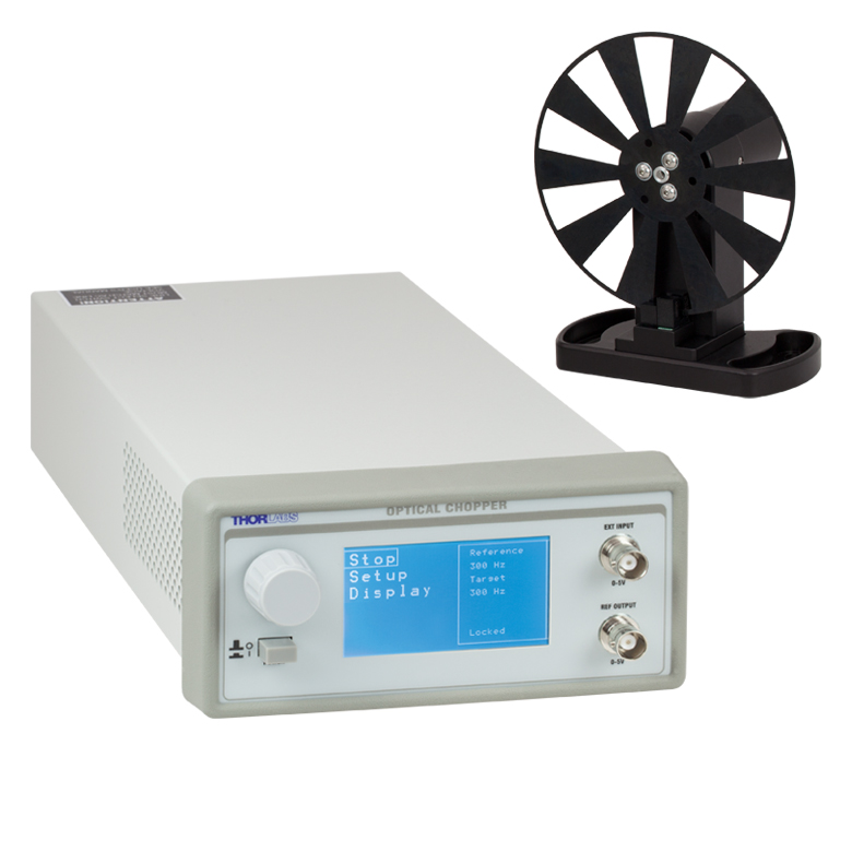
Optical Chopper System
- Crystal-Stabilized, Phase-Locked Feedback Loop Suppresses Low Frequency Drift and Phase Jitter
- Harmonic, Subharmonic, and Fractional Harmonic Chopping with Sum and Difference Reference Outputs
- Microprocessor Controlled
- Single- and Dual-Frequency Blades Available
- Harmonic Frequency Blades Available for Pump-Probe and Other Nonlinear Experiments
- Save and Recall User Setups in Non-Volatile RAM
- USB Interface
- Control Software Package Included
| Key Specifications | |
| Chopping Frequency, with Various Blades |
4 Hz – 10 kHz |
| Frequency Drift | <20 ppm/°C |
| Ext. Reference Compatibility |
TTL/CMOS |
| Frequency Resolution | 0.01 Hz (2 Slot Blades) 0.1 Hz (MC1F10HP, Default Blade) 1 Hz (All Other Blades) |
| External Reference Signal Synchronization | |
| Harmonic | 2 to 15X |
| Subharmonic | 1/2 to 1/15X |
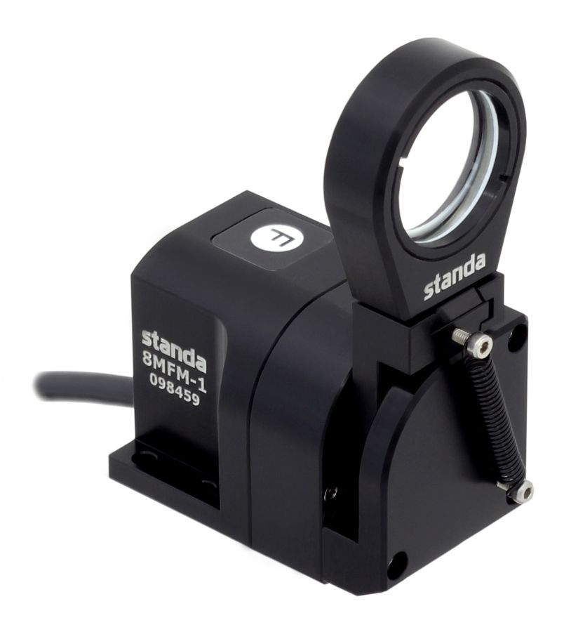
Motorized Filter Flip Mounts
- Lens Holder Included
- MFF101(/M) Includes One LMR1(/M) Ø1″ Lens Mount
- MFF102(/M) Includes One LMR2(/M) Ø2″ Lens Mount
- Compatible with All LMR Series and FMP Series Mounts up to 2.0″ Optic Diameter
- Velocity Feedback for Smooth Transitional Motion
- Mechanical Hard Stops for Repeatable Positioning
- 8-32 (M4) Tap for Post Mounting
- Flipper Unit Has Small 30 mm x 30 mm Cross Section
- Remote Handset with 39″ (1 m) Cable, APT Software Suite, and Power Supply Included
| Specifications | |
| Flip Positions | 0° and 90° |
| Flip Timea | 500 ms to 2800 ms |
| Optic Diameterb | MFF101: 1″ MFF102: 2″ |
| Flip to Flip Repeatability | 50 μrad |
| Maximum Driftc | 1.0 µm2 |
| Maximum Loadd | 120 g (4.23 oz) |
| Maximum Torque | 0.1 N•m |
| DIG I/O Connector Typee | SMA (2 Places) |
| Power Input | 15 VDC |
| Weight (Excluding Power Supply) |
100 g (3.53 oz) |
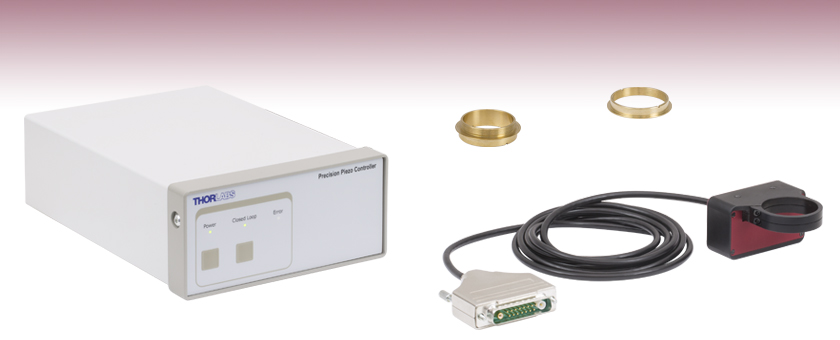
Piezo Objective Scanner
- Fast Acquisitions and High Frame Rates Enabled by 25 ms Typical Settling Time
- Maximum Clear Aperture of Ø29.0 mm Supports Large-Field-of-View Objectives
- Capacitive Feedback Sensors Provide Resolution Down to 1 nm and Help User Actively Compensate for Drift
- Quick-Release Flexure Clamps Allow Fast Objective Exchange
- Compatible with Upright, Inverted, and Rotating Microscopes
- Standalone Kinesis® and APT™ Interfaces, ThorImage®LS Integration, and Control via External Voltage
- Software Permits Easy Tuning for Different Objective Weights
| Piezo Objective Scanner Specifications | |
| Open-Loop Travel Range | 600 µm ± 10% |
| Closed-Loop Travel Range | 450 µm |
| Open-Loop Resolution | 1 nm |
| Closed-Loop Resolution | 3 nm |
| Maximum Clear Apertureb | Ø29.0 mm (Ø1.14″) |
| Maximum Objective Diameter | 38.4 mm (1.51″) |
| Maximum Loadc | 500 g (1.1 lbs) |
| Settling Time | 25 ms (Typical) for 1 – 100 µm Steps |
| Resonant Frequency | 120 Hz ± 20% for 150 g Load |
| Position Linearity Error | ±0.05% |
| Tilt Angle | X-Axisd: ±35 µrad Y-Axise: ±15 µrad |
| Capacitance | 8.0 µF ± 15% |
| Cable Length | 6 ft (2 m) |
| Dimensions | 2.72″ x 2.36″ x 1.38″ (69.0 mm x 60.0 mm x 35.0 mm) |
| Weight | 380 g (0.84 lbs) |
| Operating Temperature Range | 5 to 40 °C |
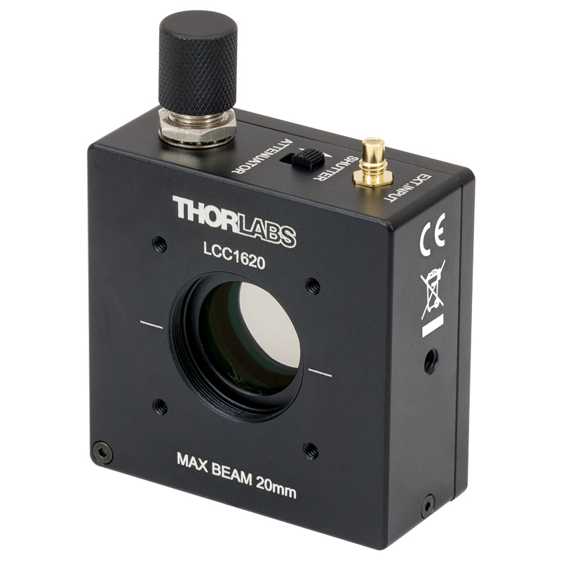
Liquid Crystal Optical Beam Shutter / Variable Attenuator
- Liquid Crystal Optical Shutter and Variable Attenuator for 420 – 700 nm Light
- Vibration-Free Device with No Moving Parts
- High Average Transmittance (>60%) and Contrast Ratio (8000:1) Over Operating Wavelength Range
- Shutter and Attenuator Modes
- Fast Shutter Switching Speeds (Shutter Mode):
- Opening: 5 ms
- Closing: 1 ms
- Post Mountable and 30 mm Cage System Compatible
- SM1 (1.035″-40) Threaded for Compatibility with Lens Tubes
| Item # | LCC1620(/M) | |
| Operating Wavelength Range | 420 – 700 nm | |
| Transmissiona (Shutter Mode, Avg.) | >60% | |
| Contrast Ratiob (Avg.) | >8000:1 | |
| Laser Damage Threshold | CWc | 1 W/cm (532 nm, Ø0.471 mm) |
| Pulsed (ns) | 0.1 J/cm2 | |
| Pulsed (fs) | 0.02 J/cm2 (532 nm, 76 Hz, 100 fs, Ø162 µm) | |
| Clear Aperture | Ø20 mm | |
| Surface Quality | 40-20 Scratch-Dig | |
| Max Incidence Angle | ±5° | |
| Switching Speed (in Shutter Mode)d | Opening: 5 ms (Typ.) Closing: 1 ms (Typ.) |
|
| Operating Frequency Rangee | 0 – 50 Hz | |
| Wavefront Distortion | ≤λ/4 @ 633 nm | |
| External Input | SMC Connector, 0 – 5 V, 25 kΩ Input Impedance | |
| Power Adapter | 12 VDC / 1.25 A with Power Cord | |
| AC Power Requirements | 110 – 240 VAC, 47 – 63 Hz, 0.4 A | |
| Mounting | Two #8-32 (M4) Threaded Holes for Post Mounting 30 mm Cage System Compatible Ø1″ Lens Tube Compatible |
|
| Operating Temperature | 15 to 60 °C | |
| Dimension (L × W × H) | 60 × 27 × 60 mm (2.36″ × 1.06″ × 2.36″) |
|
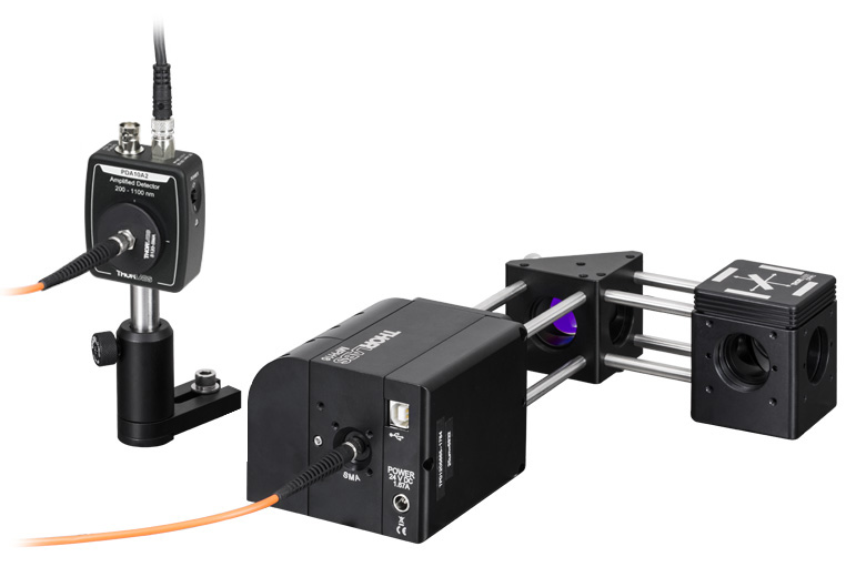
Motorized Pinhole wheel
- 16 Pinhole Sizes: Ø25 µm to Ø2 mm (See the Specs Tab for Details)
- Quick and Repeatable Pinhole Positioning
- Free Space Input Compatible with 30 mm Cage Systems (Using Dovetail Adapter)
- Fiber-Coupled Output with SMA Connector (Use Ø400 – Ø1000 µm Core MM Fiber)
- Compatible with 16 mm and 30 mm Cage Systems
| Motorized Pinhole Wheel Specifications | |
| Input Aperture | Ø10 mm |
| AR Coating on Each Surface | 350 – 700 nm, Ravg < 0.5% |
| Positioning Accuracy | ±5.1 µm |
| Material | Chrome-Plated Fused Silica |
| Pinholes | 16 (Ø25 µm to Ø2 mm) |
| Substrate Thickness | 0.020″ (0.508 mm) |
| Refractive Index | 1.5255 |
| Abbe Number (Ve) @ 546 nm | 55 |
| Recommended Fiber | Multimode Fiber, Ø400 – Ø1000 µm Core, 0.22 NA |
| Operating Voltage | 24 VDC, 1.5 A |
| Input Power (Max) | 200 mW/cm2 |
| Control | USB, Operating Software, and SDK Included |